See here for configuring a One-Arm Load Balancer
Load balancing in NSX-T isn’t functionally much different to NSX-V and the terminology is all the same too. So just another new UI and API to tackle…
As load balancing is a stateful service, it will require an SR within an Edge Node to provide the centralised service. It’s ideal to keep the T0 gateway connecting to the physical infrastructure as an Active-Active ECMP path, so this LB will be deployed to a T1 router.
The Objective
The plan is to implement a load balancer to provide both highly available web and app tiers. TLS Offloading will also be used to save processing on the web servers and provide an easy single point of certificate management.

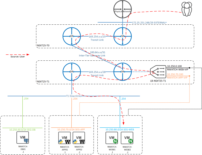
- User browses to NWATCH-WEB-VIP address
- The virtual server NWATCH-WWW-VIP is invoked and the request is load balanced to a NWATCH-WEB-POOL member
- The selected web server needs access to the app-layer servers, so references the IP of NWATCH-APP-VIP
- The NWATCH-APP-VIP virtual server forwards the request onto a pool member in NWATCH-APP-POOL
- The app server then contacts the PostgreSQL instance on the NWATCH-DB01 server and the user has a working app!
Configuration
First the WEB and APP servers are added to individual groups, that can be referenced in a pool. Using a group with dynamic selection criteria allows for automated scaling of the pool by adding/removing VMs that match the criteria:


Each group is then used to specify the members in the relevant pool to balance traffic between:

A pool then needs to be attached to a Virtual Server, which defines the IP/Port of the service and also the SSL (TLS) configuration. Here a Virtual Server is created for each service (WEB and APP):

The final step is to ensure that the new LB IPs are advertised into the physical network. As the LB is attached to a T1 gateway it must first redistribute the routes to the T0, which is done with the All LB VIP Routes toggle:

Next is to advertise the LB addresses from the T0 into the physical network, which is done by checking LB VIP under T0 Route Re-distribution:

Here’s confirmation on the physical network that we can see the /32 VIP routes coming from two ECMP BGP paths (both T0 SRs), as well as the direct Overlay subnets:

Traffic Flow
There’s now a lot of two letter acronyms in the path now from the physical network to the back end servers, there’s T0, T1, DR, SR, LB, so what does the traffic flow actually look?
The first route into the NSX-T realm is via a T0 SR, so check how it knows about the VIPs: 
It can see the VIP addresses coming from a 100.64.x.x address, which in NSX-T is a subnet that’s automatically assigned to enable inter-tier routing. In this case the interface is connected from the T0 DR to the T1 SR:

So the next stop should be the T1 gateway. From the T1 SR the VIP addresses are present under the loopback interface:

So the traffic flow for this Inline Load Balancer looks like the below:
The Final Product
Testing from a browser with a few refreshes confirms the (originally HTTP-delivered) WEB and APP servers are being round-robin balanced and TLS protected:


And the stats show a perfect 50/50 balance of all servers involved:

